latching circuit line diagram
Laser Tripwire Security Alarm Using NE555 Timer IC. 8 Images about Laser Tripwire Security Alarm Using NE555 Timer IC : What are Protective Relays? | Types and Working, 110 and 220V AC LED Voltage Indicator | Electronic Circuits Diagram and also DC 5V/12V/24V 1 Channel Latching Relay Module With Touch Bistable.
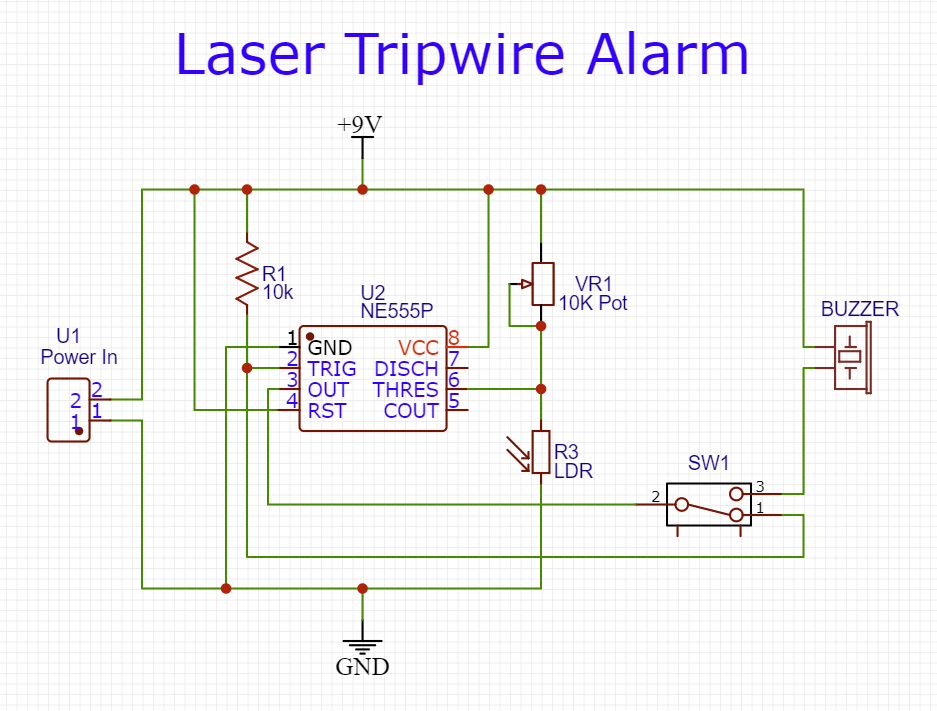
Laser Tripwire Security Alarm Using NE555 Timer IC
 circuits-diy.com
tripwire ne555 explanation
110 And 220V AC LED Voltage Indicator | Electronic Circuits Diagram
 streampowers.blogspot.com
led indicator ac 220v voltage circuit diagram 240vac circuits gr
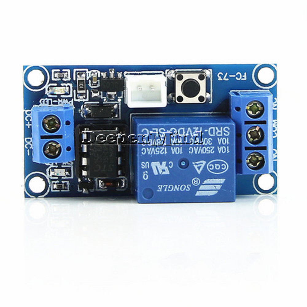
DC 5V/12V/24V 1 Channel Latching Relay Module With Touch Bistable
 www.ebay.it
latching 5v srd 12vdc 24v bistable datasheet mcu relè bistabile
Crash Course: How To Wire A KA Float Switch For Simplex Pump Control | APG
 www.apgsensors.com
switch wiring diagram float wire control pump tank ka simplex connect sensor line 2l switches apg relay power contactor fill
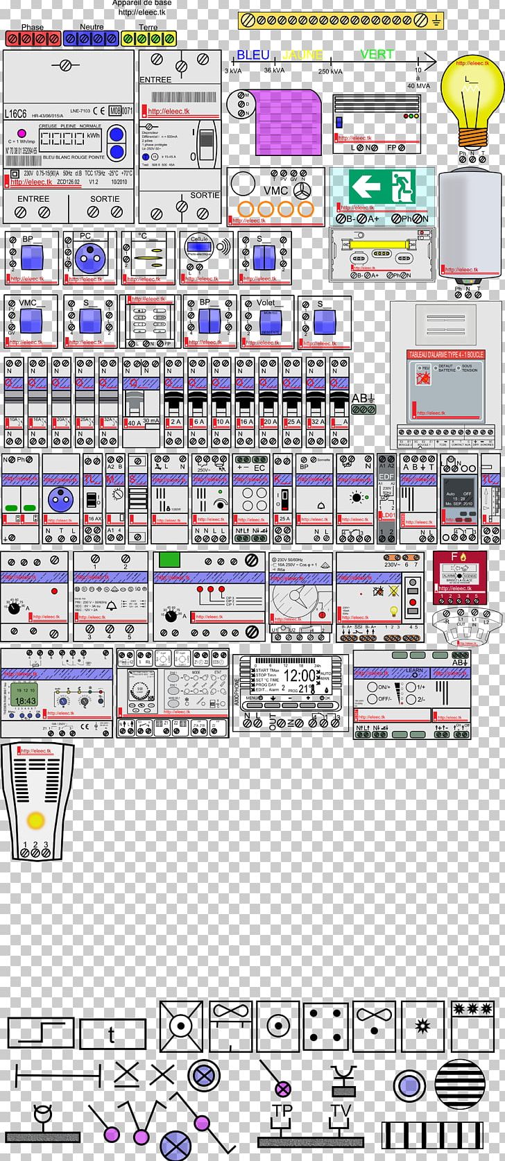
Electronic Symbol Electricity Meter Circuit Diagram PNG, Clipart, Angle
 imgbin.com
circuit diagram symbol electricity meter electronic imgbin
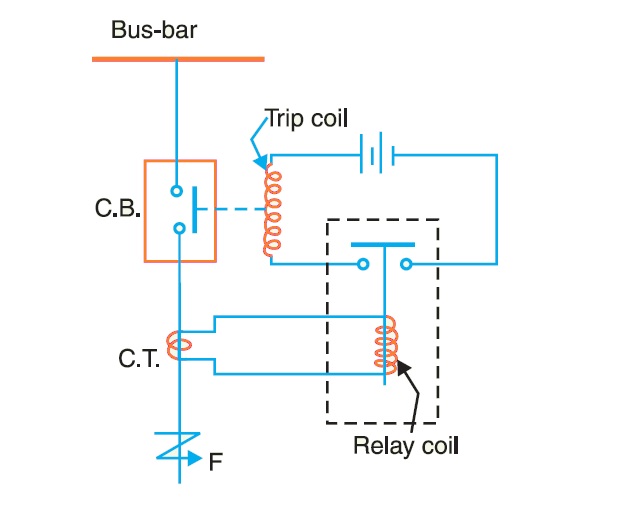
What Are Protective Relays? | Types And Working
 studyelectrical.com
protective relays relay circuit diagram electrical working typical system phase types figure
DC 5V 12V 24V 1-Channel Latching Relay Module With Touch Bistable
 www.ebay.com.au
relay latching 12v dc module channel 24v 5v mcu control bistable switch touch 1pcs
DC 5V 12V 24V 1-Channel Latching Relay Module With Touch Bistable
 www.ebay.com.au
relay 12v channel 24v latching dc module 5v mcu bistable switch touch power supply introduction
110 and 220v ac led voltage indicator. Relay 12v channel 24v latching dc module 5v mcu bistable switch touch power supply introduction. Dc 5v/12v/24v 1 channel latching relay module with touch bistable